(This article is an updated revision of my original post on this subject here.)
Why Voltage Drop Testing?
- It’s a fast, accurate, reliable, and professional test for finding unwanted resistance.
- It leaves you with a simple YES or NO answer.
- It can help separate an expert technician from a noob.
- It saves countless hours of stress, wrench-throwing, and parts-swapping!
Even though this article is focused on starting system voltage drop testing, the theory and application of the test still applies to virtually all basic circuit troubleshooting tests.
A Quick Summary of This Article
To many, electricity is confusing. I personally think of voltage testing as pressure testing instead. The term “voltage drop” is simply just “pressure testing” parts of a circuit to find where pressure is trying to bypass in a circuit. And even better, it can narrow the problem down to the EXACT electrical circuit component or connection where the unwanted resistance occurs. Still fuzzy on this? Don’t worry, I’ll explain.
First, Turn Your Voltmeter Into a Pressure Gauge and Re-Think its Usage as a Testing Tool
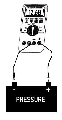 Grab any battery not in use and place your voltmeter leads across the battery posts. POOF!! Your voltmeter is magically now a pressure gauge.
And… you also just did a voltage drop test. You found pressure (voltage) bypassing the battery’s insulated plastic case through your meter.
If your battery is really dirty and wet, try moving around one of the leads on the battery’s surface with the other lead still attached to either battery post. You will likely see very, very small voltage. Why? Because the dirty wet surface is allowing a tiny bit of continuous current flow. Clean that battery!
TIP: It is not important which direction the positive or negative voltmeter leads are placed while testing. They can be reversed. The meter will just show a “minus” sign during the test next to the displayed number if the leads are reversed. This has no effect on the test.
When using the voltmeter as a pressure gauge, you are actually seeing how much pressure the battery is using to try and push electricity THROUGH your voltmeter.
Your voltmeter has, by design, extremely high resistance (about 35+ million or more ohms) built into it to prevent the battery from moving too much electricity through it. A very, very, very tiny amount of current (about 0.00000002 amps – can’t even light up a tiny test light bulb with that) is now flowing through the voltmeter from one battery post to the other.
Let’s face it. Pressure is just more easily understood and less confusing than the term ‘voltage.’ When we check a tire for air storage, we look at its pressure. When we test fuel systems, we look at pump pressure. Why make our job any harder using electrical terminology you may not be comfortable with?
In our example image, the meter reads 12.68 volts, or 12.68 “psi.” All we did was make a simple electrical bypass circuit by placing the voltmeter leads across the battery posts. While we did this, electricity couldn’t find any other easier way to go from one post to the other, so instead, it finds a way by pushing an extremely small amount of electricity through our connected voltmeter leads.
Quick, Easy Starter Circuit Refresher
Normal starter circuit in action: Turn the ignition key to crank. The battery will push electricity through the entire starter circuit (cables, starter, etc.) and return it back to the battery with ease. In other words, nothing in the starter circuit that’s not designed to be there is resisting the battery from pushing, so the starter works properly. If you happen to watch a voltmeter connected only across the battery posts, you will see the battery’s pressure drop quite a bit during cranking. This is obvious when the headlights are on too, right? A starter requires A LOT of electricity flow, so low battery pressure is normal during normal starter circuit flow.
Now think about running water through a garden hose without a nozzle. When the hose isn’t kinked, water flows just fine – like the ideal starter circuit. When you kink the hose, a lot of pressure will build before that kink, right?
Slow-turning starter, or no-turning starter in action: Assuming a fully-charged battery is used, the battery will try to push electricity through the starter circuit and return it back to the battery, but somewhere in that circuit, pressure is building up behind a blockage (or kink on the garden hose). In other words, there is something in the starter circuit – unwanted resistance – that’s not designed to be there, and it’s resisting (blocking) against the battery.
Unwanted resistance will cause a lack of current flow of electricity to and from the starter while cranking. If the starter didn’t crank normally, or it cranked too slow, or even not at all, unwanted resistance other than a bad starter could be the blame.
But where do we start looking for the problem? Easy! By doing pressure tests with our voltmeter while engaging the starter circuit to see where the high pressure is building up.
Watch The Voltage Drop Test In Action
Here’s a quick 2-minute video of a person performing a starter circuit pressure test. Watch it first, then we’ll break it down to understand what he’s doing, why he’s doing it, and how to isolate the exact problem. After reading the above, you might already understand what you’re seeing now that you look at a voltmeter as a pressure gauge.
NOTE: I do not know this person at all, but I did request use of his video in the video’s comments. Here’s a link to his YouTube channel. I know there are a LOT of other videos about this online, but so many just suck so bad. I tip my hat to this person for his application and willingness to share the knowledge.
Okay! Let’s Break This Test Down
The actual engine being tested in this video obviously was not experiencing any starting problems because it cranked normally and quickly. But know the voltage drop “pressure” test he did can be done regardless of a good or bad starting circuit.
First, Know The Testing Rules:
- Use only a digital multimeter or voltmeter. Analog meters (old meters with a moving needle) are too low in resistance and will not provide enough accuracy in this test. And don’t even think about using a test light!
- The starter circuit has to be actively engaged during this test. In other words, you have to try to start the engine while watching the voltmeter, even if the starter isn’t working – which is ideal, really. After all, that’s why you’re doing the test, right?
- Disable the engine from actually starting. If your engine’s starter actually won’t turn, or it turns slowly, then perfect! Nothing more to be done to disable the engine because you only need a few seconds to test for pressure. But if your engine starts within a second or two, you will need more time to do the voltage drop test. In this case, find a way to disable the engine, like “clear-flood mode” or disabling the fuel pump or something. Remember to clear possible codes when done.
In This Video…
Our man is first testing the battery ground circuit only to see if he can find any kind of unwanted resistance between the battery negative post and the engine block – the other end of the battery negative cable. Remember, he is using the voltmeter as a bypass circuit. This sets up the voltmeter as a pressure gauge to catch any pressure trying to push around the battery cable or ground connections.
One voltmeter lead is first placed on the negative battery clamp, but it really should be placed onto the battery negative post instead. The negative cable clamp could have a bad connection too. In fact, if I was doing this test, I’d first check the battery cable connections. They never get dirty, right? I would just place one lead on the negative battery post and the other onto the battery negative cable clamp and crank the engine. If I see any pressure over 0.1 to 0.2 volts, I know there is unwanted resistance there and those connections need cleaning.
Back to the video…now the other voltmeter lead is fastened to the starter case bolt which is also on the battery negative, or ground side. Note it may be better and easier in the real world to connect that lead to an easily accessible clean metal engine part elsewhere instead. After all, the battery negative cable connects to the engine block somewhere.
Before he cranked it over, notice there is zero voltage. This circuit is not live yet so that’s correct. Our man now cranked the engine for a few seconds making the battery ground cable alive with electricity, and he watched the voltmeter (pressure gauge) screen. The starter cranked over the engine with a normal fast starter rhythm. The voltmeter shows less than 0.50 volts (or pressure) on the voltmeter indicating no issues at all.
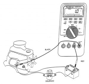 TIP: Manufacturers do have specifications for voltage drop. But as a rule of thumb for normal vehicles (higher limits for diesels), most OEM battery cables can have up to 0.50 volts of pressure maximum trying to go through your voltmeter while cranking. If you connect two cables together say through an old Ford starter solenoid, each cable can have up to 0.5 volts of pressure loss (or voltage drop) totaling 1 volt. Also, if somebody replaced an OEM cable with one that’s too skinny, you will show higher than normal voltage – like maybe 2-3 volts or more while cranking!
While our man was cranking the engine, our pressure gauge (the voltmeter) showed us almost no pressure trying to push through our voltmeter. Why? Because it was easier for the battery to push electricity through the negative battery cable connected between the meter leads than it was to push electricity through the voltmeter bypass circuit. This is exactly what we want – electricity going where it was designed to go – through the battery cable and not our voltmeter.
To test the positive circuit, simply repeat the steps above except place one voltmeter lead on the positive battery post and the other lead directly onto the positive battery cable connection on the starter motor.
So Why Was Voltage Showing If The Test Was Good?
If that negative battery cable in the video had unwanted resistance in it somewhere between the two voltmeter leads while cranking, the voltmeter (pressure gauge) will show you a higher pressure than say a normal range of 0.10 to 0.30 volts. The reason you see his voltmeter averaging around 0.2 volts pressure is because the battery cable’s copper wiring has a tiny bit of resistance in it, but it is at an acceptable, designed resistance level. Copper is a very good electrical conductor, but it is not perfect. It still has very small amounts of resistance in the metal, but that resistance isn’t normally visible unless a massive amount of electricity if flowing through it.
FAQs
Q: What are the steps to do a voltage drop test?
A:
- Ensure the battery is healthy and fully charged.
- Disable the engine from starting. You only need to crank the engine a few seconds to do each test.
- Be sure every time you connect voltmeter leads, the connections are to clean metal!
- Always test with your voltmeter across battery cable connections first. For top posts, this is easy. For a side post battery, jam the pointed lead behind the weatherpack to hit the lead battery post cleanly. Poke the other lead through the cable insulation just past the connector bolt. Either post type, crank the engine. Should get less that 0.1 volts.
- Test the negative circuit with your voltmeter from the battery negative post to the engine block and crank the engine. Should get less than 0.5 volts, but really around 0.2 to 0.3 volts is normal. (Diesel engines could be about 0.8 volts!)
- Test the positive circuit with your voltmeter from the battery positive post to the positive post stud on the starter and crank the engine. Should get less than 0.5 volts, but really around 0.2 to 0.3 volts is normal. (Diesel engines could be about 0.8 volts!) (And that you, Les Fetter for commenting and catching my Step #6 mistake here saying “to the engine block” instead of the starter post. Copy/paste error from Step #5 on my part!)
TIP: If you find higher than normal voltage during your test, it is unwanted resistance. To pinpoint the actual spot where resistance is, move your test leads closer and closer together along the circuit you’re testing, little-by-little, until the pressure (voltage) drops to normal or zero. The spot that it drops is just AFTER the exact spot of the resistance you’re looking for!
Q: Why is a voltmeter used instead of an ohmmeter?
A: An ohmmeter (resistance tester) uses its own tiny internal battery to flow electricity measuring resistance, not the circuit’s power source. It is a good test for very small wires that require very small amperage, but NOT for thick battery cables! An ohmmeter just doesn’t flow enough amperage to find resistance in large conductors like battery cables. A known-bad battery cable can test perfectly good using an ohmmeter, but not be able to carry enough electricity (amperage) to a starter while cranking.
More detail about ohmmeters: An ohmmeter flows very little current to find resistance – let’s say about 0.02 amps with a 9 volt battery compared to a 12 volt battery pushing 85 amps or more through a starter circuit. For an analogy, an ohmmeter’s amperage moving through a battery cable is like driving one small car down an 85 lane empty highway. What are the chances of the ohmmeter’s current hitting a traffic jam (resistance) on a road that big? Not very good! Now compare that scenario to current flow in an actual starter circuit. It would be like driving 85 cars down that same 85 lane highway, all side-by side. One bad spot on this road will have a much higher impact on performance for sure.
Wrapping It Up
So here’s the whole key to wrap up the voltage drop test: The circuit to be tested must be a live, active circuit – the very opposite of using an ohmmeter. If there is any resistance at all between the two places your meter leads are connected to, resistance can be seen as an increase in voltage (or pressure) on the voltmeter display. Simply, the voltage on the meter rises when electricity encounters resistance somewhere between the two multimeter leads. Therefore it tries to bypass the resistance and try to go through the voltmeter instead.
About This Article
Being a former automotive instructor for a national automotive retail/repair giant, I would travel an entire region weekly, pulling in our mechs and techs for two days of paid training. When the time came to discuss “Voltage Drop Testing” in Basic Electrical class, I’d just watch and laugh as techs would squirm in their chairs. And yes, it is basic!
The funny thing is, once that evil term “Voltage Drop” became not-so-scary and pratical, it got placed into the memory bank of every smart technician.
In my next post, I’ll share a funny but true story about how I helped an 18-year seasoned ASE Certified Master Tech (and no, it’s wasn’t me) replacing batteries, starters, and cleaning cable connections in a Firebird that cranked over slower than normal.
I hope this helped you. Leave some feedback please in the comments below.
Leave a Reply